Introduction to PMX and PMD
This section explains what information PMX and PMD files consist of, how MMD interprets that information, and how babylon-mmd implements MMD's behavior.
In this document, content about how babylon-mmd implements MMD's behavior is distinguished with this block.
PMX/PMD File Overview
Polygon Model eXtended (PMX) and Polygon Model Data (PMD) files are 3D model file formats used in Miku Miku Dance (MMD).
Basically, PMX/PMD files are single binary files that contain all data except texture files.
Since these file formats have no documented specifications, only information known through reverse engineering analysis exists, so there may be minor errors.
Also, since there are no official names for each piece of information, this document arbitrarily assigns common names to each piece of information for explanation.
Differences from Modern 3D Asset Formats
Modern widely-used 3D asset formats (e.g. glTF, FBX, etc.) have structures designed to represent Scene Graphs that include 3D models. In contrast, PMX and PMD files basically contain only information for representing a single geometry-based 3D model, and do not include information for representing elements other than 3D models such as cameras, lighting, animations, and Scene Graphs.
PMX Files
PMX is an improved version of PMD that provides better structure and more features than PMD.
Currently known PMX file versions are 2.0 and 2.1.
PMX 2.1 supports various features such as Soft Body Physics, Vertex Color, PhysicsMorph, etc., but only PMX Editor supports this specification, and since MMD also does not support version 2.1, version 2.1 is not practically used.
babylon-mmd's PmxParser supports parsing PMX 2.1 files, but PmxLoader does not load them.
babylon-mmd supports most of the PMX 2.0 specification, and unprocessed data is preserved during the model loading process.
PMD Files
PMD is the previous version of PMX, with simpler structure and limited features compared to PMX.
PMX files are not backward compatible with PMD files, and it is presumed that in MMD, models loaded as PMD files are processed with separate logic from PMX files.
babylon-mmd performs the task of converting PMD files to PMX format simultaneously while PmdParser parses PMD files.
Therefore, there is no separate logic for processing PMD models, and all MMD models are processed with common logic.
PMX/PMD File Structure and Parsing Method
PMX/PMD files are Little Endian binary files containing various data types.
These files are structured in a typical Length-Prefixed format. For example, when representing Skeleton data, the number of Bones is indicated first, followed by sequential listing of each Bone's information. The size of each data can be fixed or variable length, and the order of data is always the same.
Data alignment is not enforced, and each field is stored consecutively in the binary file.
Header
The header of PMX/PMD files includes the file version, model name, comments, etc. This information serves as file metadata, used for identifying and managing models.
In the case of PMX files, English fields such as english model name and english comment exist, but are generally not well utilized.
Geometry
The geometry of PMX/PMD files is the core part of 3D model data, and only one geometry data exists per file, mainly containing information held by vertices.
Looking at the key vertex attributes in PMX structure, the main components are:
- Position: The 3D coordinates of the vertex in the model's local space.
- Normal: The normal vector of the vertex, used for lighting calculations.
- UV: The texture coordinates of the vertex, used for mapping textures onto the model.
- Additional Vec4: Additional texture coordinates or vertex color information for advanced texturing techniques. This is not present in PMD models and is not used in most PMX models either.
- Bone Weight Type: The type of bone weight used for skinning (BDEF1, BDEF2, BDEF4, SDEF, QDEF).
- Bone Index: The index of the bone that influences the vertex.
- Bone Weight: The weight of the influence of the bone on the vertex, used for skinning.
- Edge Scale: The scale of the edge, used for rendering edges in the model.
Additional Vec4 is not commonly used in MMD models. This field is often utilized in specifications added in PMX 2.1, and can be used when applying custom shaders using MikuMikuEffect (MME) in MMD.
babylon-mmd loads vertex information from MMD models.
As an exception, the Additional Vec4 field is only preserved when the mmdmodel.preserveSerializationData option is true.
Since MMD follows DirectX's UV coordinate system while Babylon.js follows OpenGL's UV coordinate system, Y Flip is applied to UV coordinates when loading MMD models.
Not only vertex information but also indices are included. This allows the geometry to be represented as an indexed mesh.
Since MMD and Babylon.js use different Winding Orders, babylon-mmd reverses the Winding Order of indices when loading MMD models.
Texture
Textures define the images applied to the model's surface in PMX/PMD files. Multiple textures can exist in a single PMX/PMD file, and textures are stored as strings representing relative paths from the directory containing the .pmx or .pmd file.
For example, in the following file structure:
- model.pmx
- textures/
  - texture1.png
  - texture2.png
In the model.pmx file, textures are stored as relative paths like textures/texture1.png, textures/texture2.png.
Based on my investigations, the texture formats supported by MMD are PNG, JPEG, BMP, TGA.
Textures stored as relative paths are handled case-insensitively in the Windows file system.
However, since URLs are case-sensitive in web environments, texture loading may fail when loading models in babylon-mmd.
To solve this, babylon-mmd provides methods to convert MMD models to BPMX or load textures using the browser File API instead of URLs.
For BMP file loaders, due to differences in BMP loader implementations between browsers and MMD, the alpha channel may be removed when loading BMP files in browsers.
To solve this, babylon-mmd provides an option to preserve the alpha channel by modifying the header when loading BMP files.
This can be enabled using the RegisterDxBmpTextureLoader function.
Material
Materials define the surface properties of models in PMX/PMD files. Multiple materials can exist in a single PMX/PMD file, and based on the PMX format, each material includes the following properties:
- Diffuse Color: The base color of the material.
- Specular Color: The color of the specular highlight.
- Shininess: The shininess of the material, affecting the size of the specular highlight.
- Ambient Color: The ambient color of the material, used for ambient lighting.
- Edge Color: The color of the edge of the material, used for rendering edges.
- Edge Size: The size of the edge, used for rendering edges.
- Texture: The index of the texture used by the material.
- Sphere Texture: The index of the sphere texture used by the material.
- Toon Texture Index: The index of the toon
- Flag: Flags indicating various properties of the material, such as whether it is double-sided or whether it uses edge rendering.
- Index Count: The number of indices used by the material.
Index Count and Submesh
PMX/PMD files can have multiple Materials for a single Geometry.
Each material defines a submesh by dividing sections of the Geometry's Indices. Specifically, each material defines the number of indices to use from the Indices buffer, and submeshes for the Geometry's Indices are defined according to the order of materials.
For example, if the indices length is 100 and the first and second materials each use 50 indices,
the first material uses indices[0] ~ indices[49] and
the second material uses indices[50] ~ indices[99].
babylon-mmd implements MMD model submeshes using Babylon.js's MultiMaterial and SubMesh.
However, since this approach has poor compatibility with Babylon.js and may have performance issues, an option to split a single geometry into multiple geometries at load time is also provided.
This option can be enabled through the mmdmodel.optimizeSubmeshes option and is enabled by default.
Rendering Method
MMD materials are rendered in the order listed in PMX/PMD files using Depth Test, Depth Write, and Alpha Blending.
babylon-mmd provides the following rendering methods to reproduce MMD's rendering approach while offering better performance or integrating with existing Babylon.js scenes:
DepthWriteAlphaBlending- Uses Depth Test, Depth Write, and Alpha Blending identical to MMD's rendering method, rendering with Draw Order in the order listed in PMX/PMD files.
AlphaEvaluation- Respects Babylon.js's rendering approach by determining materials that don't need Alpha Blend, rendering some materials as Opaque and others using Alpha Blending. Draw Order is from the closest to the farthest materials from the camera.
DepthWriteAlphaBlendingWithEvaluation(default)- Combines
DepthWriteAlphaBlendingandAlphaEvaluation, using Depth Test, Depth Write, and Alpha Blending with Draw Order in the order listed in PMX/PMD files. Materials that don't need Alpha Blend are rendered as Opaque.
- Combines
MMD's shading uses toon shading based on the Blinn-Phong shading model.
babylon-mmd uses MmdStandardMaterial, a modified version of StandardMaterial, to reproduce MMD materials.
Additionally, models can be loaded using Babylon.js's StandardMaterial or PBRMaterial.
Skeleton
Skeleton is a structure in PMX/PMD files used to apply bone-based deformation to models.
This provides functionality similar to Unity's Skinned Mesh and Unreal Engine's Skeletal Mesh.
MMD's skeleton is composed of a hierarchical structure of bones, just like a typical Skinned Mesh skeleton.
MMD skeletons have the following special properties:
Transform Order
Skeletons with hierarchical structures typically apply transforms sequentially from the top-level bones to the lower-level bones.
However, MMD's skeleton differs in that it calculates transforms in the order that bones are defined in the file. As an exception, bones that define a separate Transform Order have a different calculation order. When a bone has a separately defined Transform Order value, that value takes priority in determining the calculation order, followed by the order in which bones are listed in the file.
Generally, Transform Order is used to ensure that IK bones are calculated last.
For PMD files, bone information cannot define a separate Transform Order, and IK bones are implicitly assigned the correct Transform Order.
When Transform Order and Bone Ordering Don't Match the Actual Hierarchy
This shows an example where Transform Order is incorrect. You can see that the bone at the end follows with a one-frame delay.
MMD calculates the animated positions of bones and then references these results when calculating the next frame. This approach creates calculation delays equal to the depth of the incorrect hierarchy, but appears to work reasonably well.
Having animation calculations influenced by previous frame results makes animation outcomes unpredictable and can confuse users. Therefore, unlike MMD's implementation, babylon-mmd does not reference previous frame calculation results when computing new frames.
This implementation may be changed if it causes issues in reproducing MMD behavior.
PMX Editor also follows the same approach as babylon-mmd, not referencing previous frame results when calculating current frame bone animations.
Bone Morph
Bone Morph is a feature that rotates or moves multiple bones simultaneously by predefined specific offsets.
This feature exists in the PMX specification and is not supported in PMD.
It is primarily used to effectively manipulate body parts like fingers, where many bones need to move together.
This will be covered in detail in the Morph section below.
Append Transform
This video shows Append Transform applied to shoulders used in Semi-Standard Bone Structure. Model: YYB式初音ミク_10th_v1.02 by SANMUYYB
Append Transform allows bones that are not in a parent-child relationship to influence each other as if they were hierarchically related.
This feature exists in the PMX specification and is not supported in PMD.
Append Transform is similar to Unity's Transform Constraint component.
In the Semi-Standard Bone Structure explained later, Append Transform is utilized to implement various convenience features that help animators create animations more easily.
IK
This video demonstrates Inverse Kinematics (IK) applied to leg movements. Model: YYB式初音ミク_10th_v1.02 by SANMUYYB
Inverse Kinematics (IK) is a feature that automatically calculates joint angles by working backwards from a target position.
In MMD, IK is primarily used to easily control foot and knee movements. For example, when you specify a foot position, IK automatically calculates the angles of the knee and thigh to create a natural leg pose.
IK consists of IK Chain and IK Target:
- IK Chain: A series of bones controlled by IK (e.g., thigh → knee → ankle)
- IK Target: A bone representing the target position that IK tries to reach
Almost all MMD models have IK applied to their legs.
This allows foot movements to be maintained correctly when applying animations between models of different heights, without requiring separate retargeting.
Standard Bone Structure / Semi-Standard Bone Structure
MMD's skeleton has a standardized bone structure, divided into Standard Bone Structure (標準ボーン構造) and its extended version, Semi-Standard Bone Structure (準標準ボーン構造).
Standard Bone Structure is the standard bone structure for representing humanoid-type models in MMD, and almost all MMD models follow this structure.
Semi-Standard Bone Structure is an extended structure based on Standard Bone Structure, which appears to be mostly used in models created after 2014.
Thanks to this standardized structure, when loading MMD animations, most animations can be easily applied without additional retargeting steps.
Explanation of Standard Bone Structure
The Semi-Standard Bone Structure is as follows, and while it is similar to Unity's Humanoid Skeleton and Mixamo's Rig, there are some differences.
/**
 * refs:
 * https://learnmmd.com/http:/learnmmd.com/mmd-bone-reference-charts/
 * https://bowlroll.net/file/9611
 *
 * mmd standard bone structure:
 *
 * -全ての親: all parents (semi-standard)
 *
 *     - センター: center
 *         - グルーブ: groove (semi-standard)
 *             - 腰: waist (semi-standard)
 *                 - 上半身: upper body
 *                     - 上半身2: upper body 2 (semi-standard)
 *
 *                         - 右肩P: right shoulder parent
 *                             - 右肩: right shoulder
 *                                 - 右肩C: right shoulder child
 *                                     - 右腕: right arm
 *                                         - 右腕捩: right arm twist (semi-standard)
 *                                             - 右ひじ: right elbow
 *                                                 - 右手捩: right hand twist (semi-standard)
 *                                                     - 右手首: right wrist
 *
 *                                                        - 右中指1: right middle finger 1
 *                                                            - 右中指2: right middle finger 2
 *                                                                - 右中指3: right middle finger 3
 *
 *                                                        - 右人指1: right index finger 1
 *                                                            - 右人指2: right index finger 2
 *                                                                - 右人指3: right index finger 3
 *
 *                                                        - 右小指1: right little finger 1
 *                                                            - 右小指2: right little finger 2
 *                                                                - 右小指3: right little finger 3
 *
 *                                                        - 右薬指1: right ring finger 1
 *                                                            - 右薬指2: right ring finger 2
 *                                                                - 右薬指3: right ring finger 3
 *
 *                                                        - 右親指0: right thumb 0 (semi-standard)
 *                                                            - 右親指1: right thumb 1
 *                                                                - 右親指2: right thumb 2
 *
 *                         - 左肩P: left shoulder parent
 *                             - 左肩: left shoulder
 *                                 - 左肩C: left shoulder child
 *                                     - 左腕: left arm
 *                                         - 左腕捩: left arm twist (semi-standard)
 *                                             - 左ひじ: left elbow
 *                                                 - 左手捩: left hand twist (semi-standard)
 *                                                     - 左手首: left wrist
 *
 *                                                         - 左中指1: left middle finger 1
 *                                                             - 左中指2: left middle finger 2
 *                                                                 - 左中指3: left middle finger 3
 *
 *                                                         - 左人指1: left index finger 1
 *                                                             - 左人指2: left index finger 2
 *                                                                 - 左人指3: left index finger 3
 *
 *                                                         - 左小指1: left little finger 1
 *                                                             - 左小指2: left little finger 2
 *                                                                 - 左小指3: left little finger 3
 *
 *                                                         - 左薬指2: left ring finger 1
 *                                                             - 左薬指3: left ring finger 2
 *                                                                 - 左薬指4: left ring finger 3
 *
 *                                                         - 左親指0: left thumb 0 (semi-standard)
 *                                                             - 左親指1: left thumb 1
 *                                                                 - 左親指2: left thumb 2
 *
 *                         - 首: neck
 *                             - 頭: head
 *                                - 両目: both eyes
 *                                - 右目: right eye
 *                                - 左目: left eye
 *
 *                 - 下半身: lower body
 *                     - 腰キャンセル右: waist cancel right (semi-standard)
 *
 *                         - 右足: right leg
 *                             - 右ひざ: right knee
 *                                 - 右足首: right ankle
 *                                     - 右つま先: right toe
 *
 *                         - 右足D: right leg D (semi-standard)
 *                             - 右ひざD: right knee D (semi-standard)
 *                                 - 右足首D: right ankle D (semi-standard)
 *                                     - 右足先EX: right toe extra (semi-standard)
 *
 *                     - 腰キャンセル左: waist cancel left (semi-standard)
 *
 *                          - 左足: left leg
 *                             - 左ひざ: left knee
 *                                - 左足首: left ankle
 *                                   - 左つま先: left toe
 *
 *                          - 左足D: left leg D (semi-standard)
 *                             - 左ひざD: left knee D (semi-standard)
 *                                - 左足首D: left ankle D (semi-standard)
 *                                   - 左足先EX: left toe extra (semi-standard)
 *
 *     - 右足IK親: right leg ik parent (semi-standard)
 *         - 右足IK: right leg ik
 *             - 右つま先IK: right toe ik
 *
 *     - 左足IK親: left leg ik parent (semi-standard)
 *         - 左足IK: left leg ik
 *             - 左つま先IK: left toe ik
 */
Hip Position and Parent Relationship Differences
Generally, humanoid-type skeletons have Hip as the root and have the following structure:
- Hip
    - Spine
    - LeftUpperLeg
    - RightUpperLeg
The MMD skeleton structure corresponding to the above humanoid skeleton structure is as follows:
- センター: center **Vertex weights corresponding to the Hip area are assigned to this bone!!**
    - グルーブ: groove (semi-standard)
        - 腰: waist (semi-standard)
            - 上半身: upper body - **Corresponds to the Hip position!!**
            - 下半身: lower body
In MMD's skeleton, vertex weights for the Hip area are assigned to the center (センター) bone. However, the bone at the position corresponding to the humanoid Hip is the upper body (上半身) bone.
This different structure causes problems when applying MMD animations to non-MMD models, and to solve this, special handling must be done exclusively for the center bone.
When applying humanoid animations to MMD models, this structural difference does not cause problems.
babylon-mmd provides AnimationRetargeter, a feature for applying humanoid animations such as mixamo animations to MMD models.
It also provides HumanoidMmd, a feature for applying MMD animations to humanoid models.
HumanoidMmd performs the exception handling for the center bone mentioned above.
Shoulder Structure
- 右肩P: right shoulder parent
    - 右肩: right shoulder
        - 右肩C: right shoulder child
            - 右腕: right arm
In Semi-Standard Bone Structure, shoulders have additional Parent bones and Child bones added to make it easier to apply animations to the shoulders.
When manipulating the shoulder, these bones rotate the Child bone in the opposite direction by the amount of the Parent bone's rotation value, so that the shoulder's children are not affected by the rotation when the shoulder is rotated.
This is implemented by applying Append Transform to the Child bone and reflecting the Parent bone's rotation value.
Leg Structure
This video demonstrates Inverse Kinematics (IK) with Append Transform applied to leg movements. Model: YYB式初音ミク_10th_v1.02 by SANMUYYB
- センター: center
    - グルーブ: groove (semi-standard)
        - 腰: waist (semi-standard)
            - 下半身: lower body
                - 腰キャンセル右: waist cancel right (semi-standard)
                    - 右足: right leg
                        - 右ひざ: right knee
                            - 右足首: right ankle
                                - 右つま先: right toe
                    - 右足D: right leg D (semi-standard)
                        - 右ひざD: right knee D (semi-standard)
                            - 右足首D: right ankle D (semi-standard)
                                - 右足先EX: right toe extra (semi-standard)
- 右足IK親: right leg ik parent (semi-standard)
    - 右足IK: right leg ik
        - 右つま先IK: right toe ik
Let's look at only the right leg. The left leg has the same structure.
- 右足IK親: right leg ik parent (semi-standard)
    - 右足IK: right leg ik
        - 右つま先IK: right toe ik
In Standard Bone Structure, IK is applied to the legs.
右足IK and 右つま先IK are used as IK target bones. They represent the foot position and toe position respectively.
- 右足: right leg
    - 右ひざ: right knee
        - 右足首: right ankle
            - 右つま先: right toe
- 右足D: right leg D (semi-standard)
    - 右ひざD: right knee D (semi-standard)
        - 右足首D: right ankle D (semi-standard)
            - 右足先EX: right toe extra (semi-standard)
Only in the Semi-Standard structure, you can see that the same structure of leg bones is defined twice.
The bones with D suffix are bones for FK manipulation, and the bones without any suffix are IK Chain bones controlled by IK.
The bones with D suffix manipulate the legs by applying offsets to IK calculation results using Append Transform.
As a result, while using IK, FK can also be used together when fine adjustments are needed.
Morph
Morph is a feature that changes the shape of models, primarily used to control MMD model facial expressions and mouth shapes that are difficult to express with skeletons alone.
This is similar to Unity's Blend Shape and Blender 3D's Shape Key, but has additional functionality.
Vertex Morph
Example of Vertex Morph that changes the face shape. Model: YYB式初音ミク_10th_v1.02 by SANMUYYB
Vertex Morph is a feature that changes the model's shape by modifying vertex positions.
Bone Morph
Example of Bone Morph that moves the hand. Model: YYB式初音ミク_10th_v1.02 by SANMUYYB
Bone Morph is a feature that rotates or moves multiple bones simultaneously by predefined specific offsets. PMD does not support this specification.
Bone Morph is primarily used for efficiently controlling body parts where many bones need to move together, such as fingers.
UV Morph
UV Morph is a feature that changes the model's appearance by modifying UV coordinates. PMD does not support this specification.
This is primarily used for effects like changing texture mapping or creating animated textures.
Material Morph
Example of Material Morph that turns hair shadow mesh on and off. Model: YYB式初音ミク_10th_v1.02 by SANMUYYB
Material Morph is a feature that changes the model's appearance by modifying material properties. PMD does not support this specification.
This allows for effects like changing material colors, transparency, or other material properties during runtime.
There are also Flip Morph and Impulse Morph.
Since these were added in the PMX 2.1 specification and are rarely used in most MMD models, babylon-mmd does not implement them.
Group Morph
Group Morph is a feature that allows multiple morphs to be grouped together and controlled as a single morph.
Display Frame
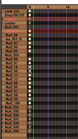
List of bones and morphs displayed in MMD's timeline panel. Model: YYB式初音ミク_10th_v1.02 by SANMUYYB
Unlike MMD, babylon-mmd does not provide animation editing functionality, so this data is not used.
This data is preserved in metadata when the mmdmodel.preserveSerializationData option is true.
Physics
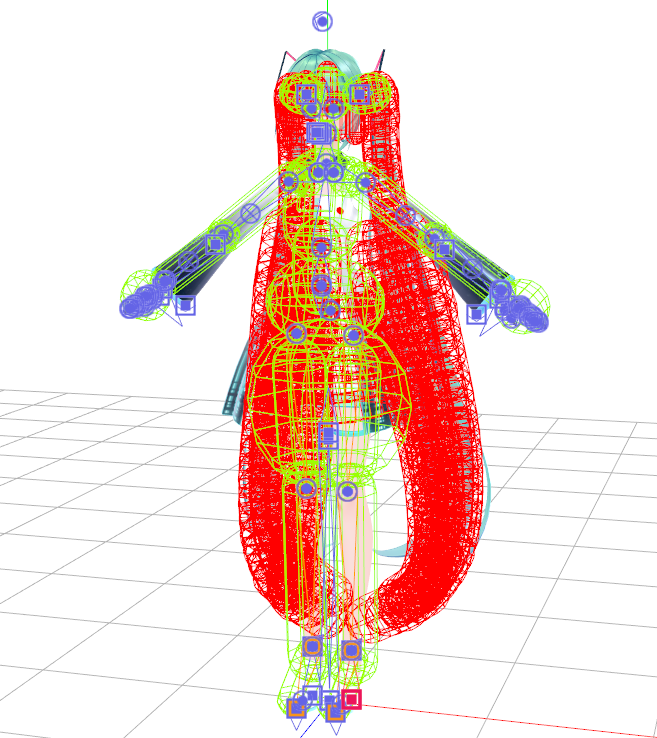
Physics Body Visualization in MMD (Yellow: Kinematic Rigid Body, Red: Dynamic Rigid Body) Model: YYB式初音ミク_10th_v1.02 by SANMUYYB
MMD uses Bullet Physics 2.75 to perform rigid body dynamics simulation to express the physical movement of model hair and clothing.
To enable this, PMX/PMD files include information about rigid bodies that reference bones and constraints that connect rigid bodies to each other.
Rigid bodies are classified into two main types: Dynamic and Kinematic.
Dynamic Rigid Body
When a specific bone is referenced by a Dynamic Rigid Body, that bone's transform ignores the hierarchy and is controlled by the physics engine.
Kinematic Rigid Body
When a specific bone is referenced by a Kinematic Rigid Body, that rigid body's transform is controlled by the bone.
Constraint
Constraints connect two rigid bodies together.
Usually, multiple rigid bodies are connected in a chain-like formation to represent hair or clothing, and constraints are used to connect them together.
babylon-mmd uses Bullet Physics 3.26.
Due to implementation differences in the Constraint Solver between Bullet Physics 3.26 and 2.75, physics calculations for some models may behave strangely in babylon-mmd.
To resolve this, babylon-mmd provides the MmdModelPhysicsCreationOptions.disableOffsetForConstraintFrame option, which allows using the 2.75 version's Constraint Solver logic.
Setting this option to true can achieve results more similar to MMD's physics calculations.
However, the 2.75 version implementation may cause artifacts where rigid bodies shake due to numerical instability.
While the PMX 2.1 specification includes SoftBody Physics specifications, as mentioned earlier, we do not discuss the 2.1 specification.